Some links on this page are affiliate links: if you buy through them we may earn a commission, at no extra cost to you.
Build a simple Arduino chronometer—a stopwatch that starts, pauses, resumes, resets, and captures a lap time. The project uses an Uno-compatible board, a 16×2 LCD, pushbuttons, and millis(); it does not need a real-time clock (RTC). In hobby projects, “chronometer” is often used loosely: this is an elapsed-time stopwatch, not a certified precision instrument or a clock that knows the time of day.
What you’ll build
The LCD shows elapsed time in hours, minutes, and seconds. One button toggles start and stop, a second resets the timer, and a third captures the current elapsed time as a lap. The lap remains visible on the second LCD row while the main timer keeps running.
The timing code uses Arduino’s millis() counter to calculate elapsed intervals rather than counting loop iterations. Arduino documents millis() and micros() among its time functions.
Recommended Free Tools
Parts
- An Arduino Uno or compatible Uno-format board
- A 16×2 HD44780-compatible parallel LCD
- Three momentary pushbuttons
- A 10 kΩ potentiometer for LCD contrast
- Breadboard, jumper wires, and a USB cable
- A backlight resistor if your LCD module requires one; check its documentation
The official LiquidCrystal library supports common HD44780-compatible text LCDs. An I²C LCD can reduce wiring, but it needs a compatible backpack and library, and its I²C address may need configuration. This tutorial uses the parallel version so the wiring and library are straightforward.
#1 Best Overall
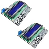
- ALL-IN-ONE DISPLAY & KEYPAD MODULE: This 1602 LCD Keypad Shield combines a 16x2 character LCD display with built-in navigation buttons (select, up, down, left, right), offering an easy-to-use interface for Arduino Uno R3/R4 and Mega boards—perfect for interactive projects, sensor monitoring, and menu navigation.
- 2-PACK FOR DOUBLE THE CREATIVITY: Includes two LCD keypad shields for Arduino, ideal for prototyping multiple Arduino projects at once. Great value for electronics hobbyists, students, and professional developers.
- SEAMLESS ARDUINO COMPATIBILITY: Fully compatible with Arduino Uno R3/R4 and Mega. The shield plugs directly onto your board with no extra wiring, making setup fast and hassle-free for both beginners and advanced users.
- CLEAR & BRIGHT 1602 LCD DISPLAY: Features a high-contrast LCD screen with two rows and sixteen characters, providing crisp and easy-to-read output for real-time data, menus, and system feedback in any lighting condition.
- FREE ONLINE TUTORIAL AVAILABLE: Get started quickly with our helpful online guide. Just search “DIYables LCD Keypad Shield” to access step-by-step instructions, example codes, and project ideas designed to support both new learners and experienced makers.
Wire the LCD and buttons
Wire the LCD in four-bit mode. LCD pin labels and physical numbering vary by module, so follow the labels printed on your display or its datasheet rather than relying only on pin position.
| LCD signal | Uno pin or connection |
|---|---|
| RS | D12 |
| E | D11 |
| D4 | D5 |
| D5 | D4 |
| D6 | D3 |
| D7 | D2 |
| VSS | GND |
| VDD | 5 V, if supported by the module |
| VO (contrast) | Potentiometer wiper; connect the other potentiometer terminals to 5 V and GND |
| RW | GND |
| Backlight | As specified for your LCD module |
For each button, connect one side to the listed digital input and the other side to GND. The sketch enables the board’s internal pull-up resistors, so you do not need a separate pull-up for each button.
| Button | Arduino pin | Other side |
|---|---|---|
| Start/Stop | D6 | GND |
| Reset | D7 | GND |
| Lap | D8 | GND |
With INPUT_PULLUP, an unpressed button reads HIGH and a pressed button reads LOW. The logic is intentionally inverted. Avoid connecting a button between 5 V and an input while using this wiring scheme.
What’s actually slowing this PC down?
Pick the symptom - the matching free tool is one click away.
Rank #2

- 35+ Guided Electronics Projects: Progress from LEDs and buttons to RFID access, real-time clocks, motion and distance sensing, environmental monitoring, motor control and interactive displays for STEM learning, coding clubs and maker projects
- More I/O and Memory for Larger Builds: The MEGA 2560 R3 provides 54 digital I/O pins, including 15 PWM outputs, 16 analog inputs, 4 hardware serial ports and 256 KB flash for projects that combine more sensors, controls and displays
- 200+ Components for Prototyping: Includes LCD1602, RC522 RFID, RTC, DHT11, HC-SR501 PIR, ultrasonic and water-level sensors, GY-521, MAX7219, keypad, joystick, rotary encoder, relay, SG90 servo, stepper motor, DC motor, breadboard and more
- Learn, Modify and Create: Follow 35+ guided lessons with example code, then adjust sensor thresholds, timing, display text, motor behavior and control logic to turn structured exercises into access systems, monitors, alarms and interactive projects
- Organized for Repeatable Learning: Pre-soldered modules, a solderless breadboard, storage case and small-parts box reduce setup time and keep sensors, LEDs, ICs, wires and other components easy to find between projects
Why use timestamps instead of delay?
A loop that calls delay(10) and adds 10 to a counter does not measure exactly 10 milliseconds per cycle: the rest of the loop takes time too. Blocking delays also make the program less responsive to button presses and harder to extend.
This stopwatch stores the time it was started and calculates the difference from the current millis() value. When paused, it adds that interval to an accumulated total. When resumed, a new interval is measured and added to the total. The display refresh runs separately, about every 100 ms; that controls how often the screen changes, not the underlying elapsed-time calculation.
Upload the sketch
- Open the Arduino IDE, connect your board by USB, and select the matching board and port.
- Paste the complete sketch below. The LCD uses Arduino’s
LiquidCrystallibrary. - Compile and upload. If
LiquidCrystal.his not found, install the library through the IDE’s library manager or check that your selected board package is installed. - Adjust the LCD contrast potentiometer until the text is readable.
#include <LiquidCrystal.h>

// LCD pins: RS, E, D4, D5, D6, D7
LiquidCrystal lcd(12, 11, 5, 4, 3, 2);

const byte START_STOP_BUTTON = 6;
const byte RESET_BUTTON      = 7;
const byte LAP_BUTTON        = 8;
const unsigned long DEBOUNCE_MS = 35;
const unsigned long DISPLAY_MS  = 100;

struct Button {
  byte pin;
  bool stableState;
  bool lastReading;
  unsigned long lastChange;
};

Button startStop = {START_STOP_BUTTON, HIGH, HIGH, 0};
Button resetButton = {RESET_BUTTON, HIGH, HIGH, 0};
Button lapButton = {LAP_BUTTON, HIGH, HIGH, 0};

bool running = false;
unsigned long accumulatedTime = 0;
unsigned long startedAt = 0;
unsigned long lastDisplayUpdate = 0;
unsigned long lapTime = 0;
bool showLap = false;

// Return true once for each debounced press (HIGH to LOW).
bool pressed(Button &button) {
  bool reading = digitalRead(button.pin);
  unsigned long now = millis();

  if (reading != button.lastReading) {
    button.lastChange = now;
    button.lastReading = reading;
  }

  if ((unsigned long)(now - button.lastChange) >= DEBOUNCE_MS) {
    if (reading != button.stableState) {
      button.stableState = reading;
      if (button.stableState == LOW) {
        return true;
      }
    }
  }
  return false;
}

unsigned long elapsedTime() {
  if (running) {
    return accumulatedTime + (millis() - startedAt);
  }
  return accumulatedTime;
}

void printTwoDigits(unsigned long value) {
  if (value < 10) lcd.print('0');
  lcd.print(value);
}

void printTime(unsigned long milliseconds) {
  unsigned long totalSeconds = milliseconds / 1000UL;
  unsigned long hours = (totalSeconds / 3600UL) % 100UL;
  unsigned long minutes = (totalSeconds / 60UL) % 60UL;
  unsigned long seconds = totalSeconds % 60UL;

  printTwoDigits(hours);
  lcd.print(':');
  printTwoDigits(minutes);
  lcd.print(':');
  printTwoDigits(seconds);
}

void setup() {
  lcd.begin(16, 2);
  pinMode(START_STOP_BUTTON, INPUT_PULLUP);
  pinMode(RESET_BUTTON, INPUT_PULLUP);
  pinMode(LAP_BUTTON, INPUT_PULLUP);

  lcd.setCursor(0, 0);
  lcd.print("Arduino Stopwatch");
  delay(1000); // Startup message only; timing and button handling are non-blocking.
  lcd.clear();
}

void loop() {
  if (pressed(startStop)) {
    if (running) {
      accumulatedTime += millis() - startedAt;
      running = false;
    } else {
      startedAt = millis();
      running = true;
    }
  }

  if (pressed(resetButton)) {
    accumulatedTime = 0;
    startedAt = millis();
    lapTime = 0;
    showLap = false;
  }

  if (pressed(lapButton)) {
    lapTime = elapsedTime();
    showLap = true;
  }

  unsigned long now = millis();
  if ((unsigned long)(now - lastDisplayUpdate) >= DISPLAY_MS) {
    lastDisplayUpdate = now;

    lcd.setCursor(0, 0);
    printTime(elapsedTime());
    lcd.print(running ? " RUN " : " STOP");

    lcd.setCursor(0, 1);
    if (showLap) {
      lcd.print("LAP ");
      printTime(lapTime);
    } else {
      lcd.print("START STOP RESET");
    }
    lcd.print("  "); // Overwrite any leftover characters.
  }
}
The code formats hours modulo 100 to fit the display. For runs of 100 hours or longer, extend the display or change the format rather than treating the displayed hour field as a total.
Rank #3

- 30+ Guided Electronics Projects: Start with LEDs and build toward LCD1602 displays, RFID access, motion detection, distance sensing, motor control and environmental monitoring for STEM learning, coding clubs, classrooms and hobby projects
- 200+ Components Across 63 Types: Includes an ELEGOO UNO R3 controller, LCD1602, RC522 RFID, RTC, HC-SR501 PIR sensor, ultrasonic sensor, DHT11, GY-521, MAX7219, keypad, joystick, relay, SG90 servo, stepper motor, breadboard and more
- Begin Without Soldering: Pre-soldered modules, a solderless breadboard, organized storage case and small-parts box reduce setup time and help beginners move from lesson to lesson while keeping LEDs, ICs, wires and sensors easy to find
- Learn, Modify and Create: Program the ELEGOO UNO R3 board with Arduino IDE using the included PDF tutorial and example code, then adjust sensor thresholds, timing, display text and motor behavior to turn guided lessons into original projects
- Flexible Power and Project Setup: Includes a 9 V, 1 A power supply, breadboard power module, 9 V battery and USB cable to support controller, breadboard and module experiments without sourcing basic setup accessories separately
Test the stopwatch
- After the startup message, press Start/Stop. The timer should begin counting.
- Press Start/Stop again. The displayed value should pause.
- Start it again. The reading should continue from its paused value.
- Press Lap while running or stopped. The second row should show the captured elapsed time while the main timer continues to behave normally.
- Press Reset. The elapsed time and lap display should clear to zero and the stopped state should remain.
- Hold a button down briefly. It should register as one press, not a stream of repeated presses.
What this stopwatch can—and cannot—measure
millis() is suitable for human-scale elapsed timing: seconds, minutes, and hours. Its unsigned-subtraction pattern also handles counter rollover for interval comparisons. For example, use (unsigned long)(millis() - previousTime) >= interval, rather than comparing against previousTime + interval. A classic 32-bit millisecond counter wraps after roughly 49.7 days; exact behavior can depend on the board core.
Do not interpret a displayed unit as a promise of measurement accuracy. Resolution is the smallest displayed or represented increment; accuracy is closeness to true elapsed time; repeatability is consistency across repeated measurements. A 35 ms debounce interval, human button motion, loop latency, electrical noise, and the board’s clock tolerance all affect when an event is recorded. This is a useful learning project and ordinary stopwatch, not sports-timing equipment or a laboratory instrument.
For short pulse-width measurements, micros() may be more appropriate, but it does not by itself make a precision instrument. The input hardware, clock, interrupt behavior, and code matter. For button-controlled timing, millis() is generally the simpler choice.
Rank #4

- A specially designed dot matrix LCD module which is used for displaying letters, numbers and symbols etc.
- Consists of several 5X7 or 5X11 other dot matrix character bits.The interval exists between each line or each bit to creat a good character spacing and row spacing effect.
- Based on HD44780 LCD chip and adopts standard 16-pin interface.
- It has a contrast adjustment knob, backlight selection switch, but also with four directional buttons, a selection button And a reset button.
- This 1602 LCD expansion board in the true sense of the circuit will be simplified, directly to the board inserted Arduino Duemilanove controller can be.
Troubleshooting
LCD shows dark blocks but no text
- Turn the contrast potentiometer slowly; an extreme setting can hide characters.
- Check that LCD RW is grounded and that VSS and VDD are connected correctly.
- Confirm the wiring matches
LiquidCrystal lcd(12, 11, 5, 4, 3, 2);and that the sketch callslcd.begin(16, 2).
Buttons seem permanently pressed or do nothing
- Confirm each button connects its input to GND when pressed; with
INPUT_PULLUP, pressed isLOW. - Check the selected pin numbers and the button’s leg layout. Many tactile buttons have paired legs on each side and must straddle the breadboard’s center gap.
- Make sure the button is not wired to 5 V instead of GND.
One press starts and immediately stops
Check for a wiring short or an incorrect button pin. The provided debounce routine waits for a stable state and reports only the transition to pressed, rather than treating every loop while held as a new press.
The timer loses time after pausing
On stop, the code must add millis() - startedAt to accumulatedTime. Replacing the start timestamp without saving that interval discards the time already measured.
The screen flickers or leaves old characters behind
Avoid clearing and redrawing the LCD on every loop. This sketch refreshes on a schedule and writes spaces after the row contents to erase leftover characters when new text is shorter.
Best Value

- TURN CODE INTO REAL-WORLD RESULTS — Follow 22+ guided lessons to make LEDs blink, read temperature and distance, move servo and stepper motors, control an LCD and respond to joystick or IR input; ideal for a family weekend build, homeschool unit, coding club or STEM classroom
- MORE PROJECT VARIETY IN ONE ORGANIZED KIT — Includes the UNO R3 controller, LCD1602 with pre-soldered header, breadboard power module, ultrasonic and DHT11 sensors, joystick, IR receiver and remote, SG90 servo, stepper motor, relay, DC motor, fan blade, displays, LEDs, buttons, resistors and jumper wires
- START WITHOUT SOLDERING — Plug-in modules, a solderless breadboard and the pre-soldered LCD help beginners focus on wiring, code and testing; the illustrated component list makes it easier to find each part and move from one lesson to the next
- LEARN THE LOGIC, THEN CREATE YOUR OWN — Use Arduino IDE and the included example code to understand digital input and output, analog sensing, timing, motor control and display functions, then change thresholds, speeds and sequences for alarms, environmental monitors, reaction games and motion projects
- CLEAR SETUP SUPPORT FOR FIRST-TIME BUILDERS — Download the latest tutorial and code, select the UNO board and correct computer port, check component polarity and breadboard rows, and keep power-module input at 9V or below; younger learners should work with an experienced adult
Choosing a board, display, or RTC
An Uno R3 or compatible Uno-format board is a straightforward starting point; the timing logic is broadly portable, but pin assignments, GPIO voltage, board cores, and display compatibility vary. Arduino’s UNO R4 WiFi and Nano R4 are alternatives with different capabilities. Check the selected board’s pin and peripheral requirements rather than assuming every Uno-format board is electrically identical.
A serial-only version can omit the LCD and report elapsed time over USB, which is useful for learning the timing logic with fewer components. An OLED can show lap lists and finer-looking readouts but needs a graphics library. A seven-segment display is easy to read at a glance but is less convenient for status messages.
An RTC is not needed to measure how long an event lasts while the Arduino is powered. Use an RTC when the project must know calendar time, preserve time through loss of board power, schedule events, or attach date-and-time stamps to records. Arduino’s Nano R4 documentation distinguishes elapsed timing with millis() from calendar-time RTC use. A DS3231 breakout is one option for an RTC project; Adafruit’s Arduino guide covers its I²C connection and RTClib setup. It does not improve the button timing in this stopwatch.
The Tool Desk
Outbyte PC Repair FREEClear out junk files and repair common Windows errorsFree Scan →Outbyte Driver Updater FREEScan for outdated or missing drivers - takes under a minuteDriver Scan →To extend this build, consider storing several lap snapshots in an array, adding a buzzer or LED for button feedback, or logging completed runs. A sensor or photogate can provide more repeatable event edges than a person pressing a button, but precision use still requires attention to the sensor, clock, and measurement method.
Quick Recap
Product prices and availability are accurate as of the date/time indicated and are subject to change. Any price and availability information displayed on Amazon at the time of purchase will apply.

